
Overview
In the first three articles of this series, we covered the Segment Routing Problem definition, Drivers, use cases, and the benefits it brings to the table. (First blog link Click Here). Then we explained Segment Routing Building Block starting with SR SID (Second blog link Click Here), and SR ADJ SID (Third blog link Click Here).
It is time now to discuss Segment Routing and LDP co-existence.
SR and LDP Interoperability
In many networks, you shall find few legacy network devices that don’t support Segment Routing however they need to be integrated with the SR domain. In order to accomplish this SR has a feature in order to integrate the LDP domain with the SR domain, which is the Segment Routing Mapping Server “SRMS“. This feature provides a mapping between the LDP labels to SR node segments in order to establish an end to end LSP stretching between the LDP and SR domains.
The below diagram outlines a sample setup to outline SR to LDP
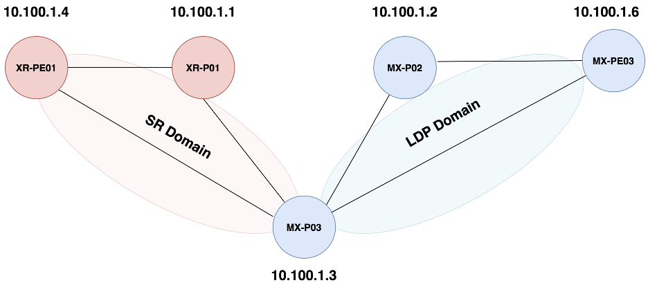
In this setup the MX-P03 is the Mapping server that we will setup in order to perform the translation between the LDP and SR domains. (In this lab, we have deployed a single SRMS for simplicity; but in real-life deployment, you must assure SRMS resiliency).
Below is output from XR-PE01 to outline there is no SR mapping for the LDP domain (MX-PE03)
RP/0/RP0/CPU0:XR-PE01#sh isis segment-routing label table
IS-IS 100 IS Label Table
Label         Prefix/Interface
----------    ----------------
400001        10.100.1.1/32
400004        Loopback0
400403        10.100.1.3/32


RP/0/RP0/CPU0:XR-PE01#sh ip cef 10.100.1.6
10.100.1.6/32, version 40, internal 0x1000001 0x0 (ptr 0xddf1fb8) [1], 0x0 (0xdfb5b28), 0x0 (0x0)
 Updated Apr 13 01:07:19.783
 remote adjacency to GigabitEthernet0/0/0/1
 Prefix Len 32, traffic index 0, precedence n/a, priority 1
   via 172.20.1.9/32, GigabitEthernet0/0/0/1, 10 dependencies, weight 0, class 0 [flags 0x0]
    path-idx 0 NHID 0x0 [0xebf5260 0x0]
    next hop 172.20.1.9/32
    remote adjacency
On the LDP domain, we can’t see any Labels for the SR domain as shown below
ansible@MX-PE03> show ldp database
Input label database, 10.100.1.6:0--10.100.1.2:0
Labels received: 3
  Label     Prefix
      3      10.100.1.2/32
     25      10.100.1.3/32
     20      10.100.1.6/32
Output label database, 10.100.1.6:0--10.100.1.2:0
Labels advertised: 3
  Label     Prefix
     57      10.100.1.2/32
     59      10.100.1.3/32
      3      10.100.1.6/32


Input label database, 10.100.1.6:0--10.100.1.3:0
Labels received: 3
  Label     Prefix
     27      10.100.1.2/32
      3      10.100.1.3/32
     21      10.100.1.6/32


Output label database, 10.100.1.6:0--10.100.1.3:0
Labels advertised: 3
  Label     Prefix
     57      10.100.1.2/32
     59      10.100.1.3/32
      3      10.100.1.6/32
In order to perform this stitching, we need to have two components
- Allocate LDP bindings for the Node-SID labels in the SR domain and have them propagated into the LDP domain
- Allocate SR bindings for the loopbacks of the nodes in the LDP domain and advertise them into the SR domain
We achieve the first part on the mapping server to advertise LDP mapping for the Node segment of the SR domain as shown below
ansible@MX-P03# set protocols ldp sr-mapping-client
We can see the effect of this command on the LDP database on the nodes in the LDP domain as shown below
ansible@MX-PE03> show ldp database
Input label database, 10.100.1.6:0--10.100.1.2:0
Labels received: 5
  Label     Prefix
     26      10.100.1.1/32
      3      10.100.1.2/32
     25      10.100.1.3/32
     27      10.100.1.4/32
     20      10.100.1.6/32


Output label database, 10.100.1.6:0--10.100.1.2:0
Labels advertised: 5
  Label     Prefix
     60      10.100.1.1/32
     57      10.100.1.2/32
     59      10.100.1.3/32
     61      10.100.1.4/32
      3      10.100.1.6/32


Input label database, 10.100.1.6:0--10.100.1.3:0
Labels received: 5
  Label     Prefix
     28      10.100.1.1/32
     27      10.100.1.2/32
      3      10.100.1.3/32
     29      10.100.1.4/32
     21      10.100.1.6/32
Output label database, 10.100.1.6:0--10.100.1.3:0
Labels advertised: 5
  Label     Prefix
     60      10.100.1.1/32
     57      10.100.1.2/32
     59      10.100.1.3/32
     61      10.100.1.4/32
      3      10.100.1.6/32

ansible@MX-PE03# run show route 10.100.1.4
inet.0: 23 destinations, 24 routes (23 active, 0 holddown, 0 hidden)
+ = Active Route, - = Last Active, * = Both

10.100.1.4/32      *[IS-IS/18] 00:03:16, metric 4000
                    > to 172.20.1.15 via ge-0/0/0.0

inet.3: 4 destinations, 4 routes (4 active, 0 holddown, 0 hidden)
+ = Active Route, - = Last Active, * = Both

10.100.1.4/32      *[LDP/9] 00:03:15, metric 1
                    > to 172.20.1.15 via ge-0/0/0.0, Push 33
Below is a snippet of a show command for the L3VPN between MX-PE03 (LDP domain) and the other end on the SR domain (XR-PE01) and we can see that an LSP is built on
ansible@MX-PE03# run show route table vpna 1.1.1.1

VPNA.inet.0: 2 destinations, 2 routes (2 active, 0 holddown, 0 hidden)
+ = Active Route, - = Last Active, * = Both


1.1.1.1/32         *[BGP/170] 00:00:36, MED 0, localpref 100, from 10.100.1.1
                      AS path: ?, validation-state: unverified
                    > to 172.20.1.15 via ge-0/0/0.0, Push 24004, Push 33(top)
We can see that the LSP is built on the LDP domain as shown below
  ansible@MX-P02# run show route table mpls.0 label 33

mpls.0: 12 destinations, 12 routes (12 active, 0 holddown, 0 hidden)
+ = Active Route, - = Last Active, * = Both

33                 *[LDP/9] 00:02:28, metric 1
                    > to 172.20.1.5 via ge-0/0/1.0, Swap 37
The Stitching between the LDP LSP and the SR is performed on the MX-P03 as shown below
ansible@MX-P03# run show route table mpls.0 label 37

mpls.0: 25 destinations, 25 routes (25 active, 0 holddown, 0 hidden)
+ = Active Route, - = Last Active, * = Both


37                 *[LDP/9] 00:00:12, metric 1
                    > to 172.20.1.2 via ge-0/0/0.0, Swap 400004
In order to build the LSP on the SR domain, we need to have Node-SID for the LDP nodes in the LDP domain. This is achieved using the SR mapping server and this mapping server will allocate Node-SID for all the nodes in the LDP domain. The configuration on Juniper NOdes is shown below
[edit routing-options]
+   source-packet-routing {
+       mapping-server-entry LDP_SR {
+           prefix-segment 10.100.1.6/32 index 406;
+           prefix-segment 10.100.1.2/32 index 402;
+       }
+   }
[edit protocols isis source-packet-routing]
+    mapping-server LDP_SR;
Once we enable the mapping server configuration on the mapping server nodes in the SR domain we can see that the Node-SID for the nodes in the LDP domain are populated in the nodes within the SR domain as shown below
RP/0/RP0/CPU0:XR-P01#sh isis segment-routing label TAble
IS-IS 100 IS Label Table
Label         Prefix/Interface
----------    ----------------
400001        Loopback0
400402        10.100.1.2/32
400403        10.100.1.3/32
400406        10.100.1.6/32


RP/0/RP0/CPU0:XR-PE01#sh ip cef 10.100.1.6
Mon Apr 13 05:38:12.178 UTC
10.100.1.6/32, version 31, labeled SR, internal 0x1000001 0x81 (ptr 0xde09fb8) [1], 0x0 (0xdfcdfa8), 0xa28 (0xe4dc368)
 Updated Apr 13 05:30:48.039
 remote adjacency to GigabitEthernet0/0/0/1
 Prefix Len 32, traffic index 0, precedence n/a, priority 1
   via 172.20.1.9/32, GigabitEthernet0/0/0/1, 6 dependencies, weight 0, class 0 [flags 0x0]
    path-idx 0 NHID 0x0 [0xec042f0 0x0]
    next hop 172.20.1.9/32
    remote adjacency
     local label 400406      labels imposed {400406}
At this stage, the Nodes in the SR domain has a corresponding label to reach each node in the LDP domain however the Router on the boundary is still not stitching between the new SR mapping and the corresponding LDP binding as shown below
ansible@MX-P03# run show route table mpls.0 label 400406
In order to implement the last change in order to stitch between the SR and LDP domain, we need to add the following configuration on MX-P03
ansible@MX-P03# run show route table mpls.0 label 400406
mpls.0: 28 destinations, 28 routes (28 active, 0 holddown, 0 hidden)
+ = Active Route, - = Last Active, * = Both


400406             *[L-ISIS/14] 00:00:01, metric 2000
                    > to 172.20.1.4 via ge-0/0/1.0, Swap 20

400406(S=0)        *[L-ISIS/14] 00:00:01, metric 2000
                    > to 172.20.1.4 via ge-0/0/1.0, Swap 20


ansible@MX-P03# run show ldp database
Input label database, 10.100.1.3:0--10.100.1.2:0

Labels received: 5
  Label     Prefix
     30      10.100.1.1/32
      3      10.100.1.2/32
     25      10.100.1.3/32
     34      10.100.1.4/32
     20      10.100.1.6/32


Output label database, 10.100.1.3:0--10.100.1.2:0
Labels advertised: 5
  Label     Prefix
     32      10.100.1.1/32
     27      10.100.1.2/32
      3      10.100.1.3/32
     39      10.100.1.4/32
     21      10.100.1.6/32
The following traceroute outline the end to end LSP from the SR to LDP domain
RP/0/RP0/CPU0:XR-PE01#traceroute vrf VPNA 192.1.1.3
Type escape sequence to abort.

Tracing the route to 192.1.1.3

 1  172.20.1.7 [MPLS: Labels 400406/18 Exp 0] 25 msec  18 msec  13 msec
 2  172.20.1.3 [MPLS: Labels 400406/18 Exp 0] 55 msec  16 msec  9 msec
 3  172.20.1.4 [MPLS: Labels 20/18 Exp 0] 48 msec  19 msec  10 msec
 4  192.1.1.3 51 msec  48 msec  44 msec
Conclusion
Based on the explanation in this blog, and Lab outcome it is clear that SR and LDP can coexist in a network domain. This is an important capability because almost all SR brownfield deployment reply in such a feature to assure service continuation when introducing SR to an LDP domain.
Stay tuned to our next blog where we will discuss SR & TI-LFA.


Leave A Comment